Products & Services
|
 |
Electronic Load
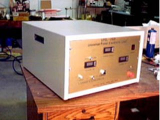
The UPEL-2500 is a bench top
electronic load simulation system that is being introduced by Electronic Design
and Research, Inc. of Louisville, Kentucky USA.
EDR’s 82573 electronic load series is designed for a DC/AC power source, power electronic devices and
component testing. The high power rating, AC/DC capability, manual and remote controls make these
loads the ideal tool for testing the high power UUT such as SMR, UPS, telecommunications equipment
manufacturers, power suppliers, drivers, battery and other power sources that operate from DC to 100 KHz.
The load is a 19” bench top model that offers manual and full remote control for easy integration into
ATE systems. An internal build-in generator produces SINE, TRIANGLE, or TOOTH waves that allow the dynamic
testing of many power sources.
Key Features:
- Power Rating: 2500W (average), 4000W maximum
- Voltage: 1 – 200V p-p
- Current: Up to 100A
- CC, CR, CV, CP load models
- Dynamic loading: up to 1KHz in AC/DC mode and up to 20 KHz in DC mode
- Measurement: Voltage (average and peak-to-peak), current and power
- Large LCD displays
- Build-in Sine, Triangle and Square wave oscillator
- APG – analog programmable interface: (1) load enable; (2) external control signal input; (3) the oscillator enable
- Full protection: 200V peak-to-peak, maximum power and maximum current
- Built in a temperature detector minimize the audio noise
- 19” rock mount
An AC/AC, AC/DC, DC/AC, and DC/DC power supplies have played a critical role on electronic devices.
The UPEL-2500 is capable of testing all sorts of DC and AC power sources. In the constant power (CP) mode the UPEL-2500
is perfectly suited for use as a discharge load for battery testing by simulating the real discharge curve.
Specification – the basic model UPEL-2500:
Case: |
19” x 23” x 12” Bench top |
| Power Rating: |
2.5KW continuous (average) and 4KW maximum |
| Voltage Rating: |
200V peak-to-peak, maximum |
| Current Rating |
100A maximum |
Features:
|
Constant current mode, Temperature controlled fans, Thermal, power and voltage cutoffs
|
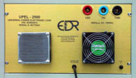 |
Back Panel |
Fuse holder, connector rated 30A with a 3.7 Ohm current limiting resistor,
connector rated at 100A with a 0.7 current limiting resistor, common connectors, and power cable |
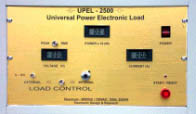 |
Front Panel |
Power switch, start/reset push-button, load/current controls, external/internal
load control switch, BNC connector for an external controls (0-10V), indicator LED, peak/RMS switch, voltage, power
and current displays |
Options:
- CR, CV and CP modes in addition to CC
- Full remote analog and logic control (DB9 connector on rear)
- A SINE, TRIANGLE and SQUARE wave generator with frequency control. Input terminals without a current limiting resistor
- Terminals for low voltage (2.4VDC) testing (only DC load)
Ordering Information:
| UPEL-2500 |
High Power DC/AC electronic load, 2.5KW, 100A/200V, constant current (CC) control. |
| Option /G |
The same as above plus a built-in SINE, TRIANGLE and SQUARE wave generator, enables input for an external control signal,
and enables input for the generator. |
| Option /V |
Option V provides built-in constant power (CP), constant voltage (CV), and constant resistance (CR) controls. A resistor-free
an additional terminal installed for a maximum allowed current at a low testing voltage. Information about voltage, current and
power is provided onto output terminals for ATE feedback. |
| Option /L |
This option has a separate terminal for a DC voltage input. |
Application specific load simulation (options)
EDR’s family of Universal Electronic Loads (UPEL) can provide constant current, constant resistant,
constant voltage and constant power modes for various application requirements.
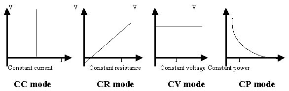
Constant Current (CC) mode
The current will remain constant no matter what the input voltage. The load only draws the current
it is set for regardless of the input voltage.
Constant Resistance (CR) mode
As the voltage changes the current is adjusted so as to maintain the same resistance at all time.
The current through the UPEL will change with The applied voltage I = V/R, where R is constant.
NOTE:
The CC and CR modes loading simulation is helpful to test whether the output voltage of a power source remains stable or
regulated under different loading current or resistance conditions.
Constant Power (CP) mode
As the voltage of the power source (Power Supply) increases the current that the UPEL draws decreases.
The current through the UPEL will change with applied voltage as I = P/V, where P is constant.
NOTE:
The CP mode simulation is essential for a battery discharge load.
Constant Voltage (CV) mode
For battery charges, the CV mode may help to change the output voltage of a charger and therefore can
test if the battery charge has the correct charging current corresponding to its own output, or in other words, the battery voltage.
Low voltage operations
EDR’s UPEL/A is designed to test both DC and AC power sources.If your application requires testing a low
voltage power supply or high speed/dynamic loading than the UPEL/D designed only to work with DC voltage must be selected.
EDR’s UPEL/D uses a closed current loop design to control a number of powerful MOSFET devices in parallel to minimize the input
impedance that enables the UPEL/D to draw a very high current at a very low voltage.It can draw up to 630A with a 2V input.
With an internal resistance of about 0.03Ohms, the major limitation to reach the maximum current could be the resistance of the
connecting wires that would be needed to connect your power source to the UPEL.
The UPEL/A works well for both AC and DC power sources but the powerful input bridge will require the
testing voltage to be at least 4V.
Dynamic loading and control
Modern electronic devices operate at a very high speed and so an electronic load should be able to perform
well in the transient and dynamic response of power devices. Both EDR’s UPELs (UPEL/A and UPEL/D) are capable to perform dynamic
testing and the UPEL/D can be controlled by an external analog control signal, which is generated by any kind of signal or
arbitrary wave-form generator. An internal (sine, triangle and square wave) oscillator allows to set a dynamic cycling up to 20 KHz.
Discounts are available for educational and quantity 5 or more units.
For further information:
Contact Us
Top of page
|